Since the optical module is not inserted in the end, the card lock on the module is not stuck, so that the device cannot recognize the optical module. After long-term operation, the module will automatically pop up or slightly collide and pop under the action of external force.
2. Optical module optical port contamination.
Due to the lack of attention to cleaning and protection during use, contaminants enter the core, causing the optical path coupling efficiency to drop or completely block the optical path, and even cause permanent damage to the core end face.
3. The light module burned out.
Since the optical module used for long-distance transmission does not have an optical attenuator when a high-power optical signal (such as an OTDR meter, a fiber self-loop, etc.) is input, the optical power exceeds the overload power of the APD tube, so that the optical module is burned.
The above operational problems may cause the optical signal to be disconnected instantaneously or for a long time, and even cause the optical module to completely fail, affecting business communication.
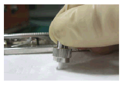
1. When installing the optical module, force the module to the end and hear the “click” sound or feel a slight vibration, indicating that the module card is stuck in place.
When the optical module card lock is not in place, the gold finger and the connector on the board are not in full contact, and the link may be connected. However, in the case of vibration, collision, etc., the optical module may be short-circuited or even loose.
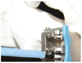
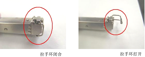
2. Refer to the handle ring state shown in Figure 1. When inserting, make sure that the handle ring is closed (the card lock is used for positioning); after inserting, pull out the optical module to check if it is installed in place. If it is not pulled out, it means it is inserted.
Figure 1 Optical module handle ring state diagram
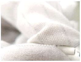
1. The site must be equipped with a rubbed paper. The jumper must be cleaned before being inserted into the optical port to avoid cross-contamination of the optical port due to contamination of the end face of the optical jumper.
Figure 2 Cleaning the fiber with special fiber paper
 Description:
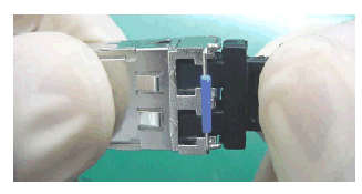
2. As shown in Figure 3, the optical module that is not in use must be equipped with a dust cap to prevent dust pollution.Place at least 3 sheets of paper on the workbench. As shown in Figure 2, wipe the fiber tip horizontally in one direction, and wipe it to another place. The wiped area can no longer be used (usually wipe a piece of rubbed paper once).
Figure 3 Installing a dust cap
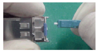
As shown in Fig. 4, the fiber can be used instead of the dust cap, and dust can be effectively prevented from entering.
Figure 4 replace the dust cap with fiber
3. As shown in Figure 5, the fiber-optic jumper that is not in use must be installed with a dust cap to avoid dust pollution, and then hang it neatly on the fiber-optic frame or into the fiber-optic package. The fiber cannot be squeezed.
Figure 5 Fiber Mounting Dust Cap
4. If the optical module or fiber is not covered with a dust cap and has not been used for a long time, the optical port or fiber must be cleaned when it is used again. As shown in Fig. 6, the optical port cleaning is performed using a cotton swab. Fiber-optic port cleaning uses abraded paper.
Figure 6 Cleaning the optical module optical port with a cotton swab
 Note: When cleaning, insert the cotton swab into the optical port and gently rotate it. Be careful not to use too much force to avoid damage to the sleeve.
5. If the signal is abnormally lost during the operation of the device, you can use the above cleaning method to clean the optical port and optical fiber of the optical module to eliminate the pollution factor.
1. When using the OTDR table to test the continuity or attenuation of the fiber path, remember to disconnect the fiber from the optical module. Otherwise, the optical module will be easily burned.
2. In the self-loop test of the board, pay attention to adding an appropriate optical attenuator. Instead of inserting the optical connector, the optical attenuator can be replaced.
1. The optical connector should be inserted vertically into the optical connector to avoid scratching the optical port.
2. Avoid the mixing of multimode, single mode fiber. Multimode devices use multimode fiber, single-mode devices use single-mode fiber, and in the case of mixed-use, signal loss and other failures occur.